Select Page
The Common Mistakes When Choosing Pressure Sensors

The Common Mistakes When Choosing Pressure Sensors

As an engineer who’s spent 15 years troubleshooting pressure sensors in industries from offshore oil rigs to pharmaceutical cleanrooms, I’ve seen how a single oversight can lead to the most common mistakes when choosing pressure Sensors, then it cause catastrophic failures, unplanned downtime, or even safety incidents.

Let’s break down the TOP-5 Mistakes When Choosing Pressure Sensors and also how to sidestep them like a pro.

Ignoring Environmental Conditions

The Mistake: Assuming a sensor rated for “industrial use” can handle everything.

The operating environment can have a significant impact on the performance and longevity of a pressure sensor.

Failing to select a sensor that can withstand the specific environmental conditions can lead to premature failure, measurement inaccuracies, and even safety concerns.

Why It’s Deadly: 

  • A sensor in a Norwegian offshore wind farm froze solid at -30°C because it was only rated for -10°
  • Dust in a Texas cement plant clogged unsealed sensors, causing erroneous readings in pneumatic systems.

Take India Market for Example

Firstly, India’s climate varies from Thar Desert heat (50°C+) to Kerala’s monsoons (90% humidity). Pressure Sensors in Punjab’s agriculture or Gujarat’s chemical plants face dust, humidity, and thermal cycling indeed;

Secondly, Mumbai’s air carries 5–10 mg/m²/day of NaCl.  If use

  • 304 SS: Fails in 6–12 months.
  • 316L SS: Lasts 2–3 years.
  • Titanium (Grade 5): 10+ years.
  • Chemical Exposure: Gujarat’s chemical zones (e.g., Dahej) need PTFE seals for acids like H2SO4.

The Fix: 

Thoroughly understand your application’s specific pressure requirements, environmental conditions, and integration needs.

  • Temperature: Choose pressure sensors rated for at least 20% beyond your min/max operating temps. For cryogenic apps, look for -196°C compatibility, for very hot temperature apps, look for +135℃, or even +200℃ solution, like EST330S or EST380 series thin-film sensing
  • Dust/Moisture: IP67 (dust-tight) or IP69K (steam-resistant) enclosures. If you are not familiar with ingress protection class, please refer to our post here: The Ultimate Knowledge about Ingress Protection (IP Rating)
  • Vibration: Use piezoresistive sensors (e.g., ESS319, or EST330S) with >100 g shock resistance for heavy machinery.
  • Material: Try to use aluminum oxide (Al₂O₃) ceramic diaphragms (ESS501, ESS502 are kind of this type for reference) for thermal stability; Try to use Conformal Coating of Silicone gel coatings (₹500/sensor) protect PCBs from humidity; Don’t use 304 stainless steels in coastal areas; Try to use SS316 or Titanium Alloy in case of salt spray corrosion areas.

Mismatched Pressure Ranges

The Mistake: Selecting a 0–100 psi pressure sensor for a system that normally runs at 60 psi or 450psi.

One of the most frequent errors I’ve observed is when users fail to accurately determine the appropriate pressure range for their application. Selecting a sensor with an inadequate pressure range can lead to inaccurate readings, early failure, or even catastrophic system damage.

Why It’s Deadly: 

Case 1: Selecting a pressure sensor with a larger range than the actual pressure

Reduced Measurement Accuracy and Resolution:

A pressure sensor with a 0-300 psi range may have a typical accuracy of ±0.5% of the full scale, which translates to an accuracy of ±1.5 psi. However, if the actual pressure range is only 0-100 psi, the same ±1.5 psi accuracy becomes ±1.5% of the full scale, significantly degrading the measurement precision.

Increased Sensitivity to Noise and Interference:

The sensor’s signal-to-noise ratio (SNR) is typically inversely proportional to the pressure range. A sensor with a 0-300 psi range may have an SNR of 60 dB, whereas the same sensor with a 0-100 psi range may have an SNR of 72 dB, providing better immunity to noise and interference.

Case 2: Selecting a pressure sensor with a smaller range than the actual pressure

Sensor Saturation and Measurement Errors:

A pressure sensor with a 0-100 psi range may have a maximum overload pressure of 150 psi. Exposing the sensor to pressures beyond 150 psi can cause the sensing element to become permanently damaged, resulting in complete loss of functionality.

Potential Catastrophic Failures:

Pressure sensors often have a burst pressure specification, which is the maximum pressure the sensor can withstand without rupturing or causing permanent damage.

Exceeding the burst pressure can result in the sensor’s complete destruction, with the potential for cascading failures in the overall system.

The Fix

To avoid these issues, it is crucial to carefully select a pressure sensor with a range that closely matches the expected pressure range in your application. This ensures accurate and reliable measurements, protects the sensor from damage, and maintains the overall system’s safety and integrity.

Rule of Thumb: Max operating pressure ≤ 70% of sensor’s full scale.

Safety Margin: For dynamic systems (e.g., hydraulic presses), use sensors with 3x burst pressure ratings.

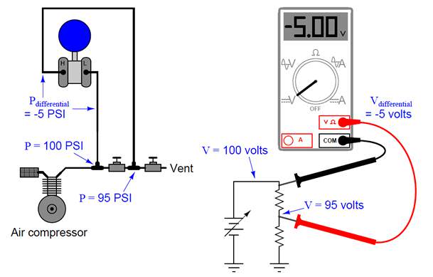
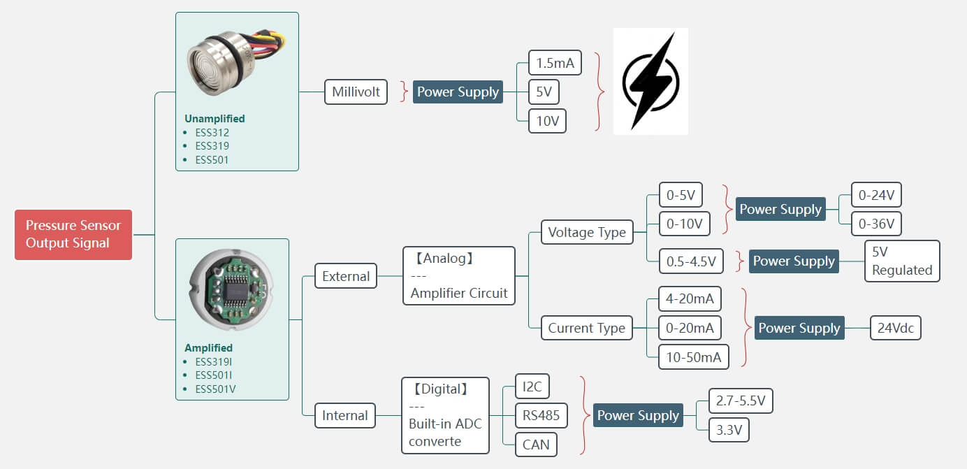
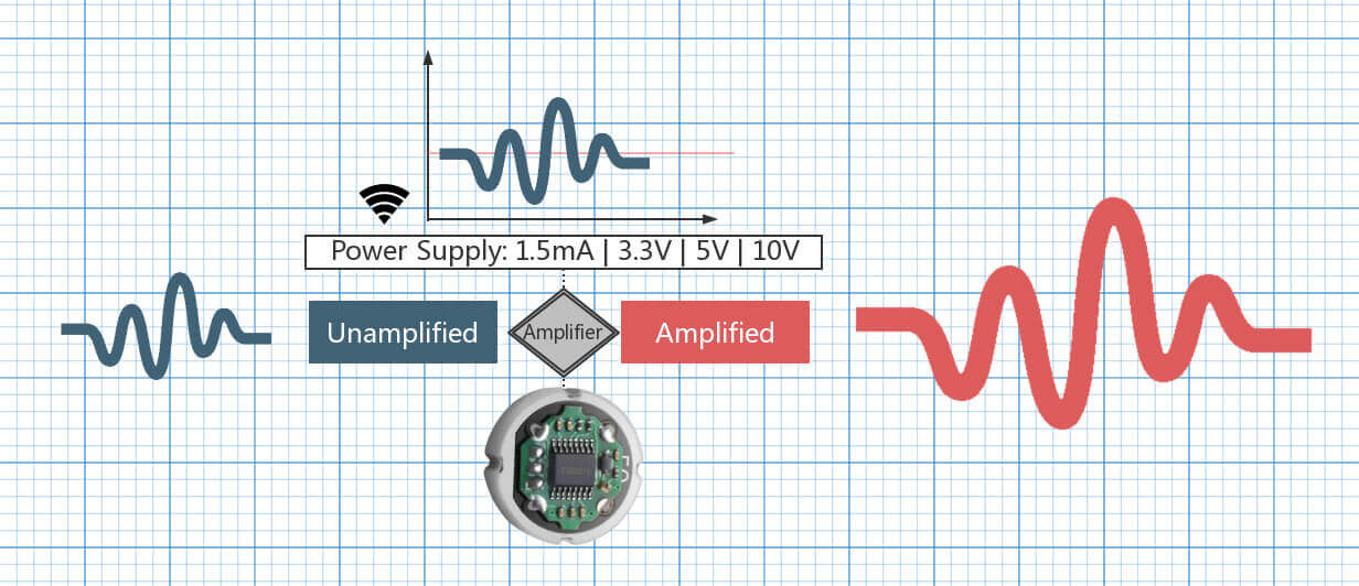
Overlooking Output Signals

The choice of pressure sensor output type is a critical factor that can significantly impact the overall performance, integration, and reliability of a pressure monitoring system.

Neglecting the pressure sensor’s output signal characteristics can have significant consequences, ranging from measurement inaccuracies and integration challenges to potential damage to the sensor or the receiving electronics.

Let’s dive into the details:

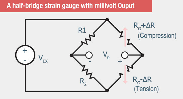
Millivolt (mV) Output:

Pressure sensors with millivolt outputs typically require additional signal conditioning and amplification circuitry to interface with data acquisition systems or control panels.

Overlooking the need for proper signal conditioning can lead to issues such as low signal-to-noise ratio, susceptibility to electromagnetic interference (EMI), and potential measurement inaccuracies.

Avoid in

Mv output is NOT recommend to be used in industrial factories with heavy machinery (e.g., motors, welding stations).

Why?

That is because mV signals (e.g., 10–100mV) are easily drowned out by electromagnetic interference (EMI) from nearby equipment.

Example:

A hydraulic press monitoring system using mV-output sensors in a factory floor reported erratic pressure spikes due to EMI from adjacent motors. Replacing them with 4–20mA sensors resolved the noise issues.

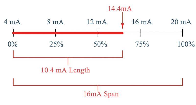
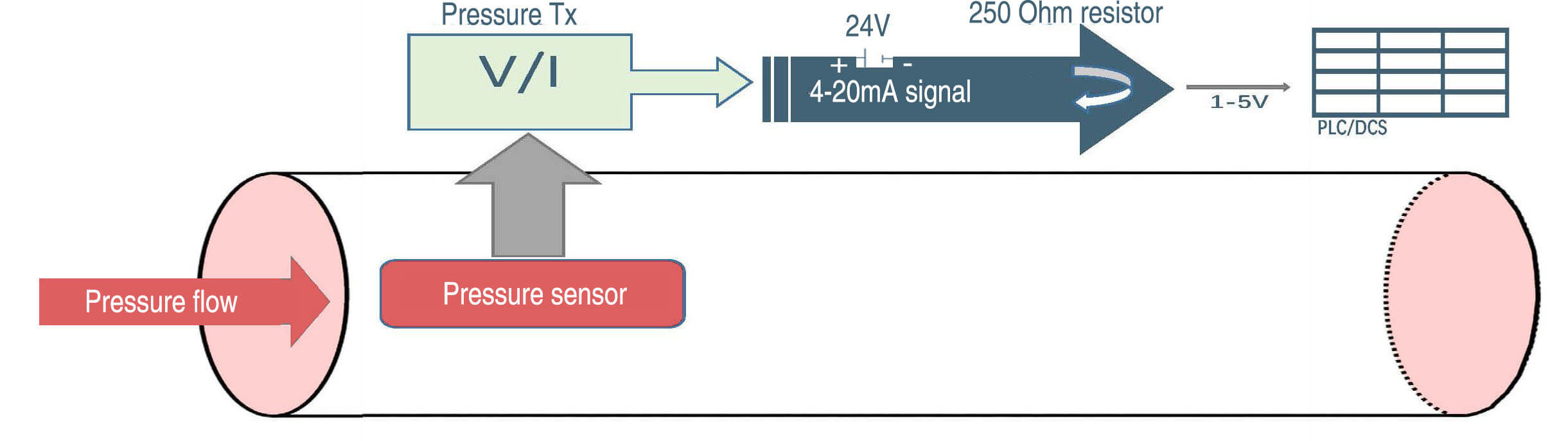
4-20 mA Current Loop Output:

Current loop outputs, like 4-20mA, are widely used in industrial applications due to their immunity to noise and voltage drops over long cable runs.

Ignoring the need for a compatible current loop interface in the receiving device can prevent successful integration and data acquisition.

Avoid in:

4-20mA output is NOT recommend to be used in case of short-distance, battery-powered IoT devices (e.g., portable environmental monitors).

Why?

4–20mA requires a constant power supply and a minimum loop resistance (e.g., 250Ω). Battery-powered systems drain quickly.

Example:

A solar-powered water level sensor using 4–20mA failed within days due to excessive power draw. Switching to a low-power LoRaWAN digital output extended battery life to months.

Click to find more details about Current Output.

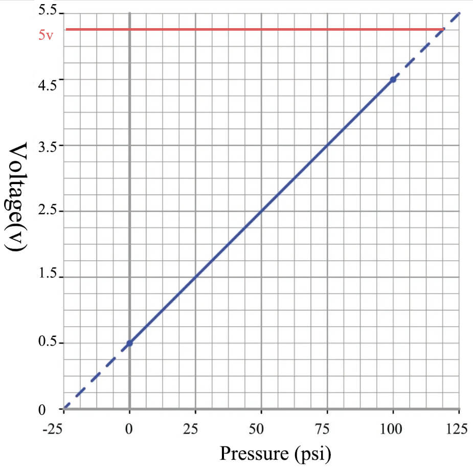
Voltage Outputs (0-5 V, 0.5-4.5 V, 0-10 V):

Voltage output pressure sensors are commonly used in various applications, but their performance can be affected by factors such as input impedance, voltage drops, and electrical noise.

Overlooking the voltage output range and the input requirements of the receiving device can lead to signal clipping, reduced resolution, or even damage to sensitive electronics.

Avoid in:

0–5V or 0–10V voltage output is NOT recommend to be used in case of long-distance cable runs (e.g., offshore oil rigs monitoring subsea pressure).

0.5–4.5V Output do NOT suite for systems without diagnostic capabilities (e.g., basic HVAC controls).

Why? 

0–5V or 0–10V voltage drops over long wires (due to cable resistance) distort readings.

The 0.5V “live zero” indicates sensor health. Systems ignoring this miss faults like sensor disconnects.

Example: A 0–10V sensor measuring pipeline pressure 500m offshore showed a 15% error due to voltage drop.

Replacing it with a 4–20mA loop eliminated the error. 

A building HVAC system using 0.5–4.5V sensors failed to detect a faulty pressure sensor (stuck at 0V), leading to a boiler overpressure incident.

Click to find more details about Voltage Output

Digital Interfaces (I2C, SPI, UART):

Digital pressure sensors offer advanced features, such as linearization, temperature compensation, and digital communication.

Failing to properly configure the communication protocols, address settings, and timing parameters can prevent successful integration and data acquisition from the pressure sensor.

Avoid in:

I2C output is NOT recommended in factory automation with long cable runs (e.g., conveyor belt systems).

Why?

I2C/SPI protocols are designed for short distances (<1m). Long cables cause signal degradation and data loss.

Example: A packaging machine using I2C pressure sensors on a 10m conveyor suffered constant communication errors. Switching to CAN Bus sensors fixed the issue.

Click to find more details about I2C Output

Wireless Protocols (IoT, ZigBee, LoRa):

Wireless pressure sensors provide the advantage of reduced wiring and increased mobility, but they require compatibility with the appropriate wireless communication technologies.

Overlooking the wireless protocol, signal strength, coverage, and power management requirements can lead to connectivity issues, data loss, or premature battery depletion.

Avoid in:

ZigBee is NOT recommended in sparse node environments (e.g., agricultural fields with few sensors).

Why?

ZigBee relies on a dense mesh network. Sparse deployments create dead zones.

Example: A farm irrigation system using ZigBee sensors had frequent dropouts due to large gaps between nodes. LoRaWAN’s long-range connectivity solved the problem.

Pressure Sensor Output signal-2

Underestimating Power Needs

The stable performance of pressure sensor hinges on one critical factor: proper power supply design. Different output signals (4-20mA, 0-10V, digital protocols, etc.) have unique power needs. Ignoring these requirements can lead to catastrophic failures or misleading data.

4-20mA Current Loop

Like mentioned earlier, the 4-20mA current loop is the gold standard for industrial sensors due to its noise immunity and long-distance reliability. The sensor regulates current, not voltage, to represent pressure.

The Mistake

  • Using a low-voltage power supply (e.g., 12V) for a sensor requiring 24V.
  • Skipping loop-powered configurations (e.g., 2-wire vs. 4-wire).

Why It’s Deadly

  • Signal Dropout: If the supply voltage is too low, the sensor can’t maintain 20mA at high pressure, causing the signal dropout.
  • Burnout: Excess voltage (e.g., 30V) in a 2-wire setup can overheat the sensor’s internal regulator.

The Fix

  • Use a 24V DC supply for most industrial 4-20mA sensors.
  • For 2-wire loops, ensure the supply voltage matches the sensor’s compliance voltage (voltage needed to drive 20mA through the loop resistance).

0-5V Voltage Output

A 0-5V output is simple and cost-effective for short-range applications (e.g., automotive sensors).

The Mistake

  • Powering the sensor with an unregulated 5V supply (e.g., a noisy USB port).
  • Using a 12V supply without a voltage regulator.

Why It’s Deadly

  • Signal Saturation: A 12V supply could fry the sensor’s op-amps or ADC, locking the output at 5V permanently.
  • Noise Corruption: Ripple from a cheap power supply adds error to the analog signal (e.g., 0.1V noise = 2% error at 5V).

The Fix

  • Use a regulated, low-noise 5V supply (e.g., linear regulator) with decoupling capacitors.
  • Add an RC filter to smooth out high-frequency noise.

0.5-4.5V Ratiometric Output

Common in automotive/MEMS sensors, the 0.5-4.5V output scales with the supply voltage (e.g., 5V).

The Mistake

  • Powering it with a variable or unregulated supply (e.g., a battery draining from 5V to 3V).

Why It’s Deadly

  • Skewed Scaling: If the supply drifts, the output range drifts too. For example, a 5V sensor reading 4.5V at full scale will drop to 3.6V if the supply falls to 4V.
  • False Zero: A sagging supply could drop the “zero” pressure output below 0.5V, making the system think there’s negative pressure.

The Fix

  • Use a stable 5V reference (e.g., precision voltage regulator) for both the sensor and the ADC.
  • Avoid sharing the supply with motors or other high-current devices.

0-10V Voltage Output

A 0-10V output is used in industrial settings for compatibility with legacy PLCs.

The Mistake

  • Using a 12V supply without a regulator, assuming 10V is close enough.”
  • Ignoring ground loops in long cable runs.

Why It’s Deadly

  • Overvoltage Damage: A 12V supply can push the sensor’s output stage beyond 10V, damaging internal components.
  • Ground Offset Errors: Even 0.5V of ground potential difference in a 10V system introduces a 5% error.

The Fix

  • Use a regulated 10V supply or a precision voltage divider.
  • Isolate the sensor’s ground from noisy equipment with an isolated DC-DC converter.

I2C Digital Output

I2C output is a common digital protocol for low-speed, short-distance communication (e.g., IoT devices).

The Mistake

  • Mixing 3.3V and 5V logic levels without level-shifting.
  • Using a noisy switching supply near the I2C lines.

Why It’s Deadly

  • Logic Conflicts: A 5V sensor can fry a 3.3V microcontroller’s I2C pins.
  • Data Corruption: Power supply noise causes glitches in SDA/SCL lines, leading to CRC errors or frozen communication.

The Fix

  • Match logic levels (3.3V or 5V) between the sensor and host.
  • Use a linear regulator for the sensor and add pull-up resistors (2.2kΩ–10kΩ) on SDA/SCL.

RS485 Digital Output

RS485 is a robust differential protocol for long-distance industrial networks.

The Mistake

  • Powering the RS485 transceiver with the same unisolated supply as the sensor.
  • Neglecting termination resistors.

Why It’s Deadly

  • Ground Loops: Shared power/ground creates voltage differentials, corrupting the differential signal (A/B lines).
  • Signal Reflections: Missing 120Ω termination resistors causes data collisions in multi-drop networks.

The Fix

  • Use an isolated DC-DC converter to separate the sensor and RS485 transceiver power.
  • Add termination resistors at both ends of the bus.

ES power supply and output (1)

Ignoring Total Cost of Ownership (TCO)

When selecting a pressure sensor, it’s tempting to focus solely on the upfront price tag. When selecting a pressure sensor, it’s tempting to focus solely on the upfront price tag.

But  ignoring Total Cost of Ownership (TCO) —the sum of all expenses over a sensor’s lifespan—can lead to crippling hidden costs, performance failures, and even operational disasters.

Let’s dive into how cutting corners on TCO sabotages your pressure sensor’s performance and your bottom line.

What is Total Cost of Ownership (TCO)?   

TCO isn’t just the purchase price. It includes:

  • Upfront costs: Sensor price, installation, integration.
  • Operating costs: Energy consumption, calibration, maintenance.
  • Failure costs: Downtime, replacements, repairs.
  • Indirect costs: Inaccurate data, safety risks, reputational damage.

Ignoring TCO is like buying a “bargain” car that guzzles gas, breaks down monthly, and costs a fortune to repair. Here’s how it backfires for pressure sensors.

The Cheap Sensor Trap:

The Mistake

Choosing a low-cost sensor with poor build quality to save money upfront, however Upfront Savings, Long-Term Pain

How It Wrecks Performance

  • Premature Failure: Cheap materials (e.g., non-industrial-grade plastics) degrade under stress, causing drift or total failure.
  • Example: A $50 sensor failing annually vs. a $200 sensor lasting 5 years.
  • Calibration Nightmares: Low-quality sensors drift faster, requiring frequent recalibration (labor + downtime).

The Fix

Compare MTBF (Mean Time Between Failures) and warranties. Invest in sensors rated for your environment (e.g., high vibration, humidity).

Energy Inefficiency

The Mistake

Ignoring a sensor’s power draw, assuming “all sensors are the same.”

How It Wrecks Performance

  • Overheating: Power-hungry sensors generate excess heat, destabilizing measurements in temperature-sensitive applications.
  • Hidden Energy Costs: A 4-20mA sensor drawing 25mA vs. 15mA adds $100s/year in energy bills for large installations.

The Fix

Opt for low-power or loop-powered sensors (e.g., 4-20mA). Use energy-efficient signal conditioners.

Maintenance Blind Spots

The Mistake

Underestimating or ignoring the labor and downtime costs of maintenance.

How It Wrecks Performance

  • Unplanned Downtime: A failed sensor in a critical process (e.g., chemical manufacturing) can halt production, costing $10,000s/hour.
  • Complex Repairs: Sensors with proprietary connectors or firmware require specialized technicians ($$$).

The Fix

Choose sensors with:

  • Suitable & Stable performance: Give up the cheap sensor and select the most reliable model instead.
  • Good reputation & Reliable manufacturer: Choose the pressure sensor with professional knowledge and quick demanding response.

Environmental Vulnerability

The Mistake

Using an off-the-shelf sensor in harsh environments (e.g., offshore rigs, food processing).

How It Wrecks Performance

  • Corrosion: Moisture or chemicals degrade unprotected sensors, causing drift or shorts.
  • Contamination: Dust or grease clogs ports, skewing readings in HVAC or pharmaceutical systems.

The Fix

Pay for ruggedization:

  • IP67/IP68 ratings for water/dust resistance.
  • Stainless steel or ceramic diaphragms for corrosive media.

The TCO Calculator: How to Avoid the Pitfalls   

  1. Map Your Requirements: Environment, accuracy, power, protocols.
  2. Compare 5-Year Costs: Include energy, labor, downtime, and replacements.
  3. Prioritize Standards: CE/RoHS-certified sensors often have lower TCO despite higher upfront costs.

Final Thought

Pressure sensors aren’t commodities—they’re precision instruments. Treat them like the critical components they are. When in doubt, consult your supplier’s application engineers. And always, always test in real-world conditions before full deployment.

Remember: A sensor isn’t just a component. It’s a long-term partner in your system’s success.

Pressure Transmitter, Pressure Transducer and Pressure Sensor- The Ultimate Guide

Pressure Transmitter, Pressure Transducer and Pressure Sensor- The Ultimate Guide

You may not surprise, in the process of measurement and control, people have been thinking and talking about

  1. pressure transmitter,
  2. pressure transducer and
  3. pressure sensor

All these three devices can touch, sense the environment we lived, then transfer kind of electrical output signal, it is series activities from physical deformation to electrical signal sensing.

In case of that, sometime some customers or even some junior engineer make no difference among these three device, they always take the three as the same instrument, and some time you may clear know you need pressure sensor only, what on earth is the difference?

How to make correct decision to choose the right detector items without cost much?

To comprehending the difference in what these 3 terms mean is necessary to make sure the measurable device picked is right for the end application; particularly when it comes to cost, power excitation, vulnerability to noise, and also constraints around electrical wiring and installment.

In this article, I will certainly disclose the truth of how to conveniently determine which among 3 is best for you and what is the key features to make them differ with each other, all you find here is the industry rarely know, let’s begin.

Output properties

If it is just one rule, you can say that the properties of the output tell which kind the sensor is, to distinguish among the various types, it can be useful to think about

Pressure sensor is the most preliminary but critical sensing unit which followed by the features including the millivolt output (always less than 100mv when 5v or 1.5mA excitation) , relative small size, a little higher accuracy compare to it after assembled as pressure transmitter of transducer.

The working principles of pressure sensor can be categorized silicon piezo-resistive, thin-film sputtered, ceramic piezo-resistive (thick-film), metal capacitive and others, click here to find more details about different pressure sensing technology.

Pressure transducer as kind of pressure detector has been given a voltage output, which might have a size of a couple of millivolts or numerous volts (always 5v, 0.5-4.5v or 100mv).

With signal amplified pcb inside the transducer body, voltage output pressure transducer always work out 0.5-2.5v, 4.5v, 5v or even 10v output, on the contrary, millivolt output pressure transducer with no such amplification process.

Pressure transmitter, on the other hand, takes 10-30vdc as power excitation, and have a present output, normally developed for connecting to the standard 4-20mA present loop, it’ been widely utilized in industrial sensing and control.

Millivolt-output pressure transducer

As remains in the name, these transducers output in millivolts (mV). The output signal is proportional to the power excitation, as an example, if it is 5Vdc power excitation, the output can be 0-50mV with a 10mv/v output signal.

The traditional foil-type strain-gauge sensing units can create an output of concerning 2-3mV/ V, whereas today’s MEMS sensors can give about 20mV/V with excellent linearity. Any variant in pressure is determined by measuring small changes in this voltage, which is a result of tiny modifications in resistance (about 0.1%) in the strain gauges themselves.

Pressure Transmitter, Pressure Transducer and Pressure Sensor -mv output

The layout listed below programs a half-bridge strain-gauge type pressure sensor , showing the excitation voltage and also output voltage. A bigger excitation voltage, say 10V as opposed to 3V, creates a bigger output voltage.

Although the output signal of mv type pressure transducer hasn’t been amplified, it also featured a lot benefits such as competitive cost, small but compact size, on the other hand, the mv type pressure transducer provides engineers more adaptability to design the most suitable interface pcb and make it the most suitable performance in measuring process.

However, there are also some disadvantages to think about for mv pressure transducer.

What is the drawback of millivolt-output pressure transducers

  1. Need regulated excitation: Since the major output is straight proportional to the excitation, the excitation voltage have to normally be produced using a regulated power supply.
  2. Low noisy sensitivity: Due to the unamplified output signal, the capability of signal transfer is poor which easy affected by noisy, so millivolt-output pressure transducer is not typically suitable for use in electrically noisy environments.
  3. Short distance connection: As well as due to the fact that the output voltage is attenuated by the resistance in attaching wires, these wires have to be kept short, suggesting that the sensing unit must be close to the surveillance instrumentation. Regarding 3 to 6 meters is normally the maximum practicable distance.

If the link range is short, and noise is not a trouble, a millivolt-output pressure transducer or even pressure sensor can be easy to design-in, please keep it in mind, millivolt-output sensor or transducer needs a regulated power supply to avoid variations in the excitation which may impact the output in response.

You can also click here to check our previous content : Why you need Millivolt Output Pressure Transducer

Voltage-output pressure transducer

A voltage-output transducer contains extra signal boosting to boost the output voltage of the bridge to a larger amount such as 5V or 10V.

0.5-4.5V Pressure Sensor regulated 5v supply

Having a larger output, voltage-output transducers are less susceptible to noise, allowing for usage in harsher electric atmospheres. Longer attaching wires can be made use of, enabling the sensor to be additionally from the panel.

Supply voltages are typically from 8-28VDC. This allows the use of a lower-cost unregulated power supply, other than where the output is 0.5-4.5 V, which calls for a 5VDC controlled supply. Reduced current usage implies voltage output pressure transducer can be powered by battery.

A while back, no matter the traditional voltage-output pressure transducer or current-output pressure transmitter, they both no “live zero”, that means zero pressure, zero output.

However the risk with these is that the system can’t identify the difference between zero pressure or a malfunction, both case will provide zero output.

What is more, the voltage-output pressure transducer enhances the bridge signal, making it a great selection where longer cable television lengths are needed. Reduced noise vulnerability, and a lower-cost uncontrolled power supply are added advantages.

Still have question about the output for pressure transducer, you can refer to our previous article about: What do you use for pressure transducer output?

Current -output pressure transmitter

In contrast to a voltage-output pressure transducer, the pressure transmitter has a low-impedance current output, it usually has been designed to transfer analogue 4-20mA signals. The output might be developed for usage with either a 2-wire or 4-wire present loophole, as both types are popularly adopted throughout our daily life.

4-20mA Pressure Sensor-proportion

4-20mA pressure transmitter supply good electrical noise resistance (EMI/RFI), making them the best choice when the signal must be transfer in very long distance. The current-output pressure transmitter can be powered by an unregulated excitation, so accordingly the current-output type pressure transmitter is generally inappropriate for battery powered devices when running at complete pressure.

A pressure transmitter converts the voltage output to an existing signal, commonly 4-20mA. Noise sensitivity is exceptionally low as well as wire sizes can be a number of hundred meters (1000m-5000m) if no more consideration or power consumption.

Case Study: 4-20mA output pressure transmitter

Pressure Transmitter, Pressure Transducer and Pressure Sensor choosing guide -4-Eastsensor

Like the diagram show above, when the fluid passing through the duct produce 10bar pressure, a 4-20mA current output pressure transmitter has been calibrated to measure which process, the output signal can be sent from pressure transmitter that is proportional to the pressure exerted by the fluid.

mAPercentage
14mA0%
28mA25%
312mA50%
416mA75%
520mA100%

If no fluid passing through, there will be no pressure at all, the pressure transmitter then generate 4mA current output signal, on the other hand, if the full fluid through the duct, it may occur the maximal 10bar pressure which sensed by the pressure transmitter through diaphragm deformation extent, a 20mA current output signal will be sent out to the terminal, in case of that, it is easily get the conclusion that the input car of controller may be broken if no current produced.

At the same time, if the input card of controller receives any amount of current output from 4 to 20mA, a 250 Ohm resistor can make current signal converted to certain voltage proportionally. As usual, the ADC can process the voltage from range 1-5V, so here we can easily understand 4-20mA is reasonable to use without any doubt.

We can then make the conclusion that, 4-20mA currently type can help us

  • Easily detect open circuit problem, if 0mA, it will difficulty to know whether wire problem or no pressure exerted at all.
  • Easily convert current signal to 1-5Vdc.

Click to find out more details of how 4-20mA pressure transmitter works

Why need 4mA instead of 3mA or 1mA?

The pressure transmitter was working on basis of pneumatic measurement when it is firstly introduced to the industry, later on, when electronics come up to manufacture, it require at very least of 3mA to active the function, on the safe side, 4mA with little margin has been proved workable.

We use 4mA as live zero, if it too small mA like 1mA, the output current will be too undetectable or even no current at all, then more wires (3 or 4 wires) instead of 2 will requested for filed instrument which will rise the cost at some extent.

Why need 20 mA instead of 21mA or 22mA?

Taken 20mA as maximal level because on hand hand, it is energy efficiency, on the other hand, 20mA is most safety range for human hart to withstand (30mA will be kind of dangerous)

When to use current signal output instead of voltage

    • 4-20mA current output signals often has more linear ability than the voltage output signal.
    • 4-20mA current output signals has low impedance and be better noise immunity.
    • 4-20mA current output signals pressure transmitter can transfer the signal to long distance usually more than 1km.
    • 4-20mA current output signals is safe for human to withstand even the excitation is 24v or 30vdc
    • 4-20mA current output signals is intrinsically safe for hazardous location.

You can also click here to check our previous content :
What is The Difference between Pressure Transducer and Pressure Transmitter?

How to choose the right one

You may now understand that both pressure transducer and pressure transmitter are derive from pressure sensor, they all can be produced out based on the material of silicon or ceramic, designed abide by the principle of piezo-resistive or capacitive, used to measure pressure or level, sent signal either voltage or current.

For better understanding, we wrap up the main features of each in below chart.

Millivolt pressure transducerVoltage pressure transducerCurrent pressure transmitter
Signal without amplifiedModerate susceptible to noise4-20mA is used in everywhere
The lowest costLonger connection distance than millivolt pressure transducerPressure transmitter has more linear ability than pressure traducer
For short distance connection (always 3-6 meters)Shorter connection distances than pressure transmitterThe longest connection distance (always 1-5km)
Sensitive to noisyLower power consumption compares to pressure transmitterStrong immunity to noise
Needs regulated voltage (stable bridge-excitation)Needs unregulated bridge-excitation voltageHigher power consumption than pressure transducer

Except the output types for pressure measurement, you can also find more details by clicking here to find out what else need to keep in mind when choose pressure transmitter.

We can help you in Eastsensor

In Eastsensor, our experienced technical expert will be on your assistance anytime, and to help you get out of the question and problem with all they have.

ESS3 series pressure sensor always produces 50 to 100 mv as output signal (before amplified), like ESS319 for gauge pressure, ESS320 for differential pressure, ESS319T for pressure and temperature together, they all with mv output less than 100 usually.

Model
Range
Diameter
Type
Accuracy/FS
Input
Output
ESS3120-10bar-1000bar12.6mmG/A/S0.1%-0.2%1.5mA/5V/10V≤150mV
ESS319-70-0.07bar19mmG0.1%-0.2%1.5mA/5V/10V≤150mV
ESS319-1bar-0.1bar-1000bar19mmG/A/S0.1%-0.2%1.5mA/5V/10V≤150mV
ESS319-I2C-1bar-0.1bar-1000bar19mmG/A0.3%-0.5%3.3V/5V≤150mV
ESS319T0.1bar-30bar(Pressure)19mmG/A/S0.25%1.5mA/5V/10V≤150mV
-104'℉-185'℉(Temperature)0.50%
ESS319I-1bar-0.1bar-1000bar19mmG/A/S0.20%10-30V0.5-4.5V/4-20mA
ESS3200-0.35bar-35bar19mmD0.1%-0.2%1.5mA/5V/10V≤150mV
ESS322-1bar-0.1bar-1000bar28mmG/A/S0.1%-0.2%1.5mA/5V/10V≤150mV
ESS323-1bar-100bar19mmG/A/S0.1%-0.2%1.5mA/5V/10V≤150mV
ESS3310-5bar-100bar29.5mmG/A/S0.1%-0.2%1.5mA/5V/10V≤150mV
ESS332-1bar-0.1bar-35bar19mmG/A/S0.1%-0.2%1.5mA/5V/10V≤150mV
ESS3500-0.35bar-60bar50mmG/A/S0.20%1.5mA/5V/10V≤150mV
ESS3430-100pa-400bar35mmG/A/S/D0.1%-0.2%10-30V4-20mA/HART
ESS010-2bar-2200bar19mmG/A/S0.05%-0.075%1.5mA/5V/10V≤150mV

EST3 series pressure transducers always adopt either 10-30v unregulated voltage or 5v regulated voltage as excitation, produce output signal of 4-20mA and 0.5-4.5v in response.

ModelEST3110EST3110 BEST3120
EST3110EST3110BEST3120
Data SheetDownloadDownloadDownload
Range0~5bar…50bar0~5bar…50bar0~5bar…50bar
Accuracy±1.0%±1.0%,±4.0%±0.25%,±0.5%,±1.0%
Power Supply 10~30Vdc12~30Vdc10~30Vdc,5Vdc
Output 4~20mA,0.5~4.5V4~20mA,0.5~4.5V4~20mA,0.5~4.5V
Electrical ConnectionPackardM12X1/ GX12/16-7DIN43650, IP65; GX 16-7
Pressure ConnectionG1/4, NPT1/4, 7/16-20UNFG1/4, NPT1/4, 7/16-20UNFM20 x 1.5, G1/4, G1/2, NPT1/4, 7/16-20UNF
Ingression ProtectionIP65IP45/ IP65IP45/ IP68
ModelEST3122EST3135EST3123
EST3122EST3135EST3123
Data SheetDownloadDownloadDownload
Range0~5bar…50bar0~5bar…50bar0~5bar…50bar
Accuracy±0.5%±1.0%,±2.0%±0.5%,±1.0%
Power Supply 10~30Vdc,5Vdc5±0.25Vdc5Vdc
Output 4~20mA,0.5~4.5V0.5~2.5…4.5Vdc0.5~2.5…4.5Vdc
Electrical ConnectionPackard, DIN43650PackardPackard
Pressure Connection7/16-20UNF, 9/16-20UNFCooper Pipe Connection7/16-20UNF, 9/16-20UNF, M20 x 1.5, G1/4
Ingression ProtectionIP65IP65IP65

EST4 series smart pressure transmitter is based on metal capacitance sensing, the output can be 4-20mA with HART.

Span and Measuring Range
Span Pressure RangeLevel RangeGPAPDPHP
20ー0.1~1.5kpa0-10~150mmH2O**
30ー0.7~7.0kpa0-70~700mmH2O**
40ー4.0~40kpa0-400~4000mmH2O****
50ー20~200kpa0-2000~20000mmH2O****
60ー70~700kpa0-0.7~7kgf/cm2****
70ー210~2100kpa0-2.1~21kgf/cm2****
80ー700~7000kpa0-7.0~70kgf/cm2***
90ー2.1~21Mpa0-21~210kgf/cm2**
00ー4.1~41Mpa0-41~410kgf/cm2*


Pressure Transmitter Vent fittings

Pressure Transmitter Vent fittings

Let’s consider a common industrial pressure transmitter used for measuring process pressure in a pipeline carrying a liquid or gas. Now it’s time to remove the pressure transmitter, then how should we do and what need to be careful?

Safety protocols

Before removing this transmitter from live service, it’s crucial to follow proper safety protocols to avoid potential hazards.

First, we need to isolate the transmitter from the process line by closing the root valve and the bypass valve. This step ensures that no process fluid can flow into the transmitter during removal. Next, we need to vent or drain any residual pressure or fluid trapped between the closed valves and the transmitter. This is done by carefully opening the vent or drain valve, allowing the trapped fluid or gas to escape safely.

Vent Fitting

Now, let’s talk about the vent fitting itself. Imagine a small valve or opening on the transmitter body, typically equipped with a small plug or cap. This fitting is designed to allow the equalization of pressure between the internal components of the transmitter and the atmosphere.

During normal operation, this vent fitting is left open to allow proper pressure measurement.

However, when removing the transmitter, we need to be cautious about this vent fitting. If it’s left open, any residual process fluid or gas could potentially leak out, creating a safety hazard or environmental concern. To prevent this, we need to carefully close or seal the vent fitting before completely removing the transmitter.

For instance, if the vent fitting has a small screw-on cap, we would gently tighten it to seal the opening. If it’s a small valve, we would turn it to the closed position. This step ensures that any remaining fluid or gas inside the transmitter is contained and cannot escape during removal and transportation.

Safety Instruction

It’s essential to follow the manufacturer’s specific instructions for sealing the vent fitting on that particular transmitter model. Additionally, we should wear appropriate personal protective equipment (PPE) such as safety glasses, gloves, and a face shield, as a precautionary measure against any potential leaks or exposure.

By isolating the transmitter, venting or draining any trapped fluid or gas, and carefully sealing the vent fitting, we can safely remove the pressure transmitter from live service while minimizing risks to personnel, equipment, and the environment.

What else should be noted

Before removing a pressure transmitter from live service, the technician must “bleed” or “vent” accumulated fluid pressure to atmosphere in order to achieve a zero energy state prior to disconnecting the transmitter from the impulse lines.

Some valve manifolds provide a bleed valve for doing just this, but many do not. An inexpensive and common accessory for pressure-sensing instruments (especially transmitters) is the bleed valve fitting or vent valve fitting, installed on the instrument as a discrete device.

The most common bleed fitting is equipped with 1/4 inch male NPT pipe threads, for installation into one of the 1/4 inch female NPT pipe ports typically provided on pressure transmitter flanges. The bleed fitting is operated with a small wrench, loosening a ball-tipped plug off its seat to allow process fluid to escape through a small vent hole in the side of the fitting.

The following photographs show close-up views of a bleed fitting both assembled (left) and with the plug fully extracted from the fitting (right). The bleed hole may be clearly seen in both photographs:

When installed directly on the flanges of a pressure instrument, these bleed valves may be used to bleed unwanted fluids from the pressure chambers, for example bleeding air bubbles from an instrument intended to sense water pressure, or bleeding condensed water out of an instrument intended to sense compressed air pressure.

The following photographs show bleed fittings installed two different ways on the side of a pressure transmitter flange, one way to bleed gas out of a liquid process (located on top) and the other way to bleed liquid out of a gas process (located on bottom):

NOTE : The standard 3-valve manifold, for instance, does not provide a bleed valve – only block and equalizing valves.

With the bleed plug completely removed, the open bleed fitting provides a port through which one may apply air pressure for testing the response of the pressure transmitter.

A special test fitting called a bleed port adapter or DP transmitter calibration fitting – colloquially known as a stinger – threads into the opened bleed fitting.

Special fitting & Bleed port adapters

This special fitting allows a compression-style tube to be temporarily connected to the opened bleed port, which then allows the connection of an air pump and test pressure gauge to the transmitter. Thus, the bleed port adapter enables a technician to conveniently apply test pressures to the DP transmitter without having to loosen any of the instrument manifold bolts, tapered thread pipe connections, or impulse tube compression fittings.

When performing field checks of pressure transmitters, bleed port adapters substantially reduce the amount of time necessary to field-test pressure instruments. The following sequence of illustrations show how a bleed port adapter may be used in conjunction with a three-valve instrument manifold to isolate a DP transmitter from a process and then subject it to test pressures from a hand pump:

Note how both bleed vents must be opened, and the equalizing valve shut, in order to apply a test pressure to the DP transmitter.

Although it is possible to safely bleed pressure from both sides of a DP instrument through just one bleed fitting (through the open equalizing valve), both bleeds must be open in order to perform a pressure test. If the “L” side bleed fitting is left in the shut position, some pressure may be trapped there as pressure is applied to the “H” side by the hand pump. If the equalizing valve is left open, no difference of pressure will be allowed to form across the DP instrument.

Conclusion

Removing a pressure transmitter from live service requires careful planning and execution. First, isolate the transmitter by closing valves and venting or draining trapped fluid.

Carefully seal the vent fitting to contain any residual material. Verify safe operating conditions, perform leak tests, and address any issues before removal.

Follow manufacturer guidelines, use appropriate PPE, and comply with site safety protocols. Proper handling and containment during transportation are essential.

DP Transmitters Applications

DP Transmitters Applications

The combination of two differential pressure ports makes the DP transmitters very versatile as a pressure-measuring device. This one instrument may be used to measure pressure differences, positive (gauge) pressures, negative (vacuum) pressures, and even absolute pressures, just by connecting the “high” and “low” sensing ports differently.

In every DP transmitters application, there must be some means of connecting the transmitter’s pressure-sensing ports to the points in a process. Metal or plastic tubes (or pipes) work well for this purpose, and are commonly called impulse lines, or gauge lines, or sensing lines.

This is equivalent to the test wires used to connect a voltmeter to points in a circuit for measuring voltage. Typically, these tubes are connected to the transmitter and to the process by means of compression fittings which allow for relatively easy disconnection and reconnection of tubes.

Measuring Process Vessel Clogging

We may use the DP transmitters to measure an actual difference of pressure across a process vessel such as a filter, a heat exchanger, or a chemical reactor. The following illustration shows how DP transmitters may be used to measure clogging of a water filter:

DP Transmitters 01-Eastsensor

Note how the high side of the DP transmitters connects to the upstream side of the filter, and the low side of the transmitter to the downstream side of the filter. This way, increased filter clogging will result in an increased transmitter output.

Since the transmitter’s internal pressure sensing diaphragm only responds to differences in pressure between the “high” and “low” ports, the pressure in the filter and pipe relative to the atmosphere is completely irrelevant to the transmitter’s output signal.

The filter could be operating at a line pressure of 10 PSI or 10000 PSI – the only variable the DP transmitters measures is the pressure drop across the filter. If the upstream side is at 10 PSI and the downstream side is at 9 PSI, the differential pressure will be 1 PSI (sometimes labeled as PSID, “D” for differential). If the upstream pressure is 10000 PSI and the downstream pressure is 9999 PSI, the DP transmitters will still see a differential pressure of just 1 PSID.

Likewise, the technician calibrating the DP transmitters on the workbench could use a precise air pressure of just 1 PSI (applied to the “high” port, with the “low” port vented to atmosphere) to simulate either of these real-world conditions. The DP transmitters imply cannot tell the difference between these three scenarios, nor should it be able to tell the difference if its purpose is to exclusively measure differential pressure.

Measuring Positive Gauge Pressure

DP transmitters may also serve as simple gauge pressure instruments if needed, responding to pressures in excess of atmosphere. If we simply connect the “high” side of DP transmitters to a process vessel using an impulse tube, while leaving the “low” side vented to atmosphere, the instrument will interpret any positive pressure in the vessel as a positive difference between the vessel and atmosphere:

Although this may seem like a waste of the transmitter’s abilities (why not just use a simpler gauge pressure transmitter with just one port?), it is actually a very common application for DP transmitters. This usage of a differential device may not actually be a “waste” if true-differential applications exist at the same facility for that pressure transmitter, which means only one spare transmitter need be stocked in the facility’s warehouse instead of two spare transmitters (one of each type).

Most DP transmitters manufacturers offer “gauge pressure” versions of their differential instruments, with the “high” side port open for connection to an impulse line and the “low” side of the sensing element capped off with a special vented flange, effectively performing the same function we see in the above example at a slightly lesser cost.

A close-up photograph of a Rosemount model 1151GP gauge pressure transmitter shows the port-less flange on the “low” side of the pressure sensing module. Only the “high” side of the sensor has a place for an impulse line to connect:

So in this regards, the DP Transmitters can serve both differential pressure process and gauge process. This is also the main reason why people can’t tell the obvious difference between DP transmitters and Gauge transmitter if only distinguishes them from appearance.

Also read: Basics of DP Transmitter & Capacitance Differential Pressure Transmitter Working Principle

DP Transmitters 03-Eastsensor

A closer look at this flange reveals a vent near the bottom, ensuring the “low” side of the pressure-sensing capsule always senses ambient (atmospheric) pressure:

DP Transmitters 04-Eastsensor

Measuring Absolute Pressure

Absolute pressure is defined as the difference between a given fluid pressure and a perfect vacuum, as opposed to gauge pressure which is the difference between a fluid’s pressure and the atmospheric air pressure.

We may build an absolute pressure sensing instrument by taking a DP instrument and sealing the “low” side of its pressure-sensing element in connection to a vacuum chamber. This way, any pressure greater than a perfect vacuum will register as a positive difference:

DP Transmitters 05-Eastsensor

Most absolute pressure transmitters resemble “gauge pressure” adaptations of DP transmitters, with only one port available to connect an impulse line. Unlike gauge pressure transmitters, though, absolute pressure transmitters do not have vent holes on their “low” sides. The “low” side of an absolute pressure transmitter must be a sealed vacuum in order to accurately measure the “high” side fluid pressure in absolute terms.

Absolute pressure measurement is important for a variety of process applications, including boiling-point control and mass flow measurement of gases. The boiling temperature of any liquid is a function of the absolute pressure it experiences, and in applications where boiling temperature must be precisely controlled in order to achieve a certain outcome (e.g. vacuum distillation of crude oil, for example) the best type of pressure measurement to use absolute. When computing the mass flow rate of gases in a pipe, the relationship between volume and molecular count is a function of both temperature and pressure (both absolute), and so absolute pressure measurement is indispensable here as well.

Measuring vacuum

The same principle of connecting one port of  DP transmitters to a process and venting the other works well as a means of measuring vacuum (pressures below that of atmosphere). All we need to do is connect the “low” side to the vacuum process and vent the “high” side to atmosphere:

DP Transmitters 06-Eastsensor

Any pressure in the process vessel less than atmospheric will register to the DP transmitters as a positive difference (with P-high greater than P-low). Thus, the stronger the vacuum in the process vessel, the greater the signal output by the transmitter.

This last statement deserves some qualification. It used to be, the way analog pneumatic and electronic transmitters were designed many years ago, that the only way to obtain an increasing signal from a DP transmitters was to ensure the “high” port pressure rose in relation to the “low” port pressure (or conversely stated, to ensure the “low” port pressure dropped in relation to the “high” side pressure).

However, with the advent of digital electronic technology, it became rather easy to program DP transmitters with a negative range, for example 0 to −10 PSI. This way, a decreasing pressure as interpreted by the transmitter would yield an increasing output signal.

It is rare to find a pressure transmitter calibrated in such a way, but bear in mind that it is possible. This opens the possibility of using a regular “gauge” pressure transmitter (where the “high” port connects to the process vessel and the “low” port is always vented to atmosphere by virtue of a special flange on the instrument) as a vacuum instrument. If a gauge pressure transmitter is given a negative calibration span, any decreasing pressure seen at the “high” port will yield an increasing output signal.

Capacitance Differential Pressure Transmitter Working Principle

Capacitance Differential Pressure Transmitter Working Principle

Introduction

A capacitance differential pressure transmitter is a type of pressure measurement device that uses the principle of capacitance to accurately measure the difference in pressure between two points in a system. It is commonly used in various industrial applications where precise pressure monitoring and control are required.

The transmitter consists of two pressure sensing diaphragms, one on each side of the differential pressure being measured. These diaphragms are typically made of a flexible material, such as stainless steel or silicon, and are separated by a small gap. The diaphragms are designed to deform in response to changes in pressure, causing a change in the capacitance between them.

The capacitance is the ability of the diaphragms to store electrical charge, and it is directly proportional to the distance between the diaphragms. As the pressure difference across the diaphragms changes, the diaphragms move, altering the distance between them and thus changing the capacitance.

The capacitance change is then converted into an electrical signal by a sensing circuit within the transmitter. This signal is typically proportional to the differential pressure being measured and can be further processed and displayed by a control system or a human operator.

Capacitance differential pressure transmitters offer several advantages, including high accuracy, stability, and reliability. They are capable of measuring a wide range of pressure differentials and are often used in applications such as HVAC systems, industrial process control, and fluid flow measurement.

Metal Capacitance DPT

Another common electrical pressure sensor design works on the principle of differential capacitance, most of capacitance differential pressure transmitter use it.

In this design, the sensing element is a taut metal diaphragm located equidistant between two stationary metal surfaces, comprising three plates for a complementary pair of capacitors. An electrically insulating fill fluid (usually a liquid silicone compound) transfers motion from the isolating diaphragms to the sensing diaphragm, and also doubles as an effective dielectric for the two capacitors:

Eastsensor use three types of fluid compound to fill according to the requirement of measurement process, each has different temperature performance.

  • Silicone Oil 200 Temp. Range -40~149℃
  • Modified silicone oil Temp. Range 15~315℃
  • Fluorocarbon oil Temp. Range -45~205℃

Capacitance Differential Pressure Transmitter 01 - Eastsensor

Any difference of pressure across the cell causes the diaphragm to flex in the direction of least pressure. The sensing diaphragm is a precision-manufactured spring element, meaning that its displacement is a predictable function of applied force.

The applied force in this case can only be a function of differential pressure acting against the surface area of the diaphragm in accordance with the standard force-pressure-area equation F = PA.

In this case, we have two forces caused by two fluid pressures working against each other, so our force-pressure-area equation may be rewritten to describe resultant force as a function of differential pressure (P1 − P2) and diaphragm area: F = (P1 − P2)A.

Since diaphragm area is constant, and force is predictably related to diaphragm displacement, all we need now in order to infer differential pressure is to accurately measure displacement of the diaphragm.

The diaphragm’s secondary function as one plate of two capacitors provides a convenient method for measuring displacement. Since capacitance between conductors is inversely proportional to the distance separating them, capacitance on the low-pressure side will increase while capacitance on the high-pressure side will decrease:

A capacitance detector circuit connected to this cell uses a high-frequency AC excitation signal to measure the different in capacitance between the two halves, translating that into a DC signal which ultimately becomes the signal output by the instrument representing pressure.

These pressure sensors are highly accurate, stable, and rugged. An interesting feature of this design – using two isolating diaphragms to transfer process fluid pressure to a single sensing diaphragm through an internal “fill fluid” – is that the solid frame bounds the motion of the two isolating diaphragms such that neither one is able to force the sensing diaphragm past its elastic limit.

The Isolating Diaphragm

As the illustration shows, the higher-pressure isolating diaphragm gets pushed toward the metal frame, transferring its motion to the sensing diaphragm via the fill fluid. If too much pressure is applied to that side, the isolating diaphragm will merely “flatten” against the solid frame of the capsule and stop moving.

This positively limits the isolating diaphragm’s motion so that it cannot possibly exert any more force on the sensing diaphragm, even if additional process fluid pressure is applied. This use of isolating diaphragms and fill fluid to transfer motion to the sensing diaphragm, employed in other styles of differential pressure sensor as well, gives modern differential pressure instruments excellent resistance to over-pressure damage.

It should be noted that the use of a liquid fill fluid is key to this overpressure-resistant design. In order for the sensing diaphragm to accurately translate applied pressure into a proportional capacitance, it must not contact the conductive metal frame surrounding it. In order for any diaphragm to be protected against overpressure, however, it must contact a solid backstop to limit further travel.

Thus, the need for non-contact (capacitance) and for contact (overpressure protection) are mutually exclusive, making it nearly impossible to perform both functions with a single sensing diaphragm. Using fill fluid to transfer pressure from isolating diaphragms to the sensing diaphragm allows us to separate the function of capacitive measurement (sensing diaphragm) from the function of overpressure protection (isolation diaphragms) so that each diaphragm may be optimized for a separate purpose.

A classic example of a pressure instrument based on the differential capacitance sensor is the EST4300 Capacitance Differential pressure transmitter, which use ESS343 capacitance sensing element, shown in assembled form in the following photograph:

A close-up photograph shows the construction of one of the isolating diaphragms, which unlike the sensing diaphragm is designed to be very flexible. The concentric corrugations in the metal of the diaphragm allow it to easily flex with applied pressure, transmitting process fluid pressure through the silicone fill fluid to the taut sensing diaphragm inside the differential capacitance cell:

The interior of the same differential capacitance sensor (revealed by cutting a ESS343 Capacitance Sensing Element in half with a chop saw) shows the isolating diaphragms, the sensing diaphragm, and the ports connecting them together:

Metallic Capacitive Sensor 3

Here, the left-side isolating diaphragm is clearer to see than the right-side isolating diaphragm. A feature clearly evident in this photograph is the small clearance between the left-side isolating diaphragm and the internal metal frame, versus the spacious chamber in which the sensing diaphragm resides.

Recall that these internal spaces are normally occupied by fill fluid, the purpose of which is to transfer pressure from the isolating diaphragms to the sensing diaphragm. As mentioned before, the solid metal frame limits the travel of each isolating diaphragm in such a way that the higher pressure isolating diaphragm “bottoms out” on the metal frame before the sensing diaphragm can be pushed past its elastic limit. In this way, the sensing diaphragm is protected against damage from overpressure because the isolating diaphragms are simply not allowed to move any farther.

The capacitance differential pressure transmitter inherently measures differences in pressure applied between its two sides. In keeping with this functionality, this pressure instrument has two threaded ports into which fluid pressure may be applied.

A later section in this chapter will elaborate on the utility of capacitance differential pressure transmitter. All the electronic circuitry necessary for converting the sensor’s differential capacitance into an electronic signal representing pressure is housed in the blue-colored structure above the capsule and flanges. A more modern realization of the differential capacitance pressure-sensing principle is the EST4300 capacitance  differential pressure transmitter:

Remote Diaphragm Seal Pressure Transmitter single

As is the case with most of capacitance differential pressure transmitter, this instrument has two ports through which fluid pressure may be applied to the sensor. The sensor, in turn, responds only to the difference in pressure between the ports.

The differential capacitance sensor construction is more complex in this particular pressure instrument, with the plane of the sensing diaphragm perpendicular to the plane of the two isolating diaphragms. This “coplanar” design is more compact than the older style of sensor, and more importantly it isolates the sensing diaphragm from flange bolt stress.

Take particular note of how the sensor assembly is not embedded in the solid metal frame as was the case with the original EST4300 design. Instead, the sensor assembly is relatively isolated from the frame, connected only by two capillary tubes joining it to the isolating diaphragms. This way, stresses inside the metal frame imparted by flange bolts have virtually no effect on the sensor.

Process fluid pressure applied to the isolating diaphragm(s) transfers to fill fluid inside the capillary tubes, conveying pressure to the taut diaphragm inside the differential capacitance sensor. Like the classic EST4300 model design, we see the fill fluid performing multiple functions:

  • The fill fluid protects the delicate sensing diaphragm from contact with unclean or corrosive process fluids
  • The fill fluid allows the isolating diaphragms to provide overpressure protection for the sensing diaphragm
  • The fill fluid provides a medium of constant permittivity for the differential capacitance circuit to function

EST4300 Capacitance Differential Pressure Transmitters

The “super-module” series of EST4300 capacitance differential pressure transmitters shares the same coplanar design as the earlier EST4300, but adds a new design feature: inclusion of the electronics within the stainless-steel module rather than the blue-painted upper housing. This feature allows the transmitter size to be significantly reduced if needed for applications with limited space.

EST4300 Capacitance Differential Pressure Transmitter has the same function which its equivalent has. Find out details of EST4300 series, please click below links.

Also read: Basics of DP Transmitter

Basics of DP Transmitter

Basics of DP Transmitter

Introduction

Differential pressure refers to the difference in pressure between two points in a fluid system. It is the contrast between the pressure at one location and the pressure at another location within the system.

Differential pressure is commonly used in various applications to measure, monitor, and control fluid flow, level, or pressure. It is often used to determine the flow rate of a fluid through a pipe or a vessel, as the pressure difference across a restriction or an orifice is directly proportional to the flow rate.

DP Transmitter

To measure differential pressure, you can use various instruments and methods depending on the specific application. Here are a few common methods.

One of the most common, and most useful, pressure measuring instruments in industry is the differential pressure transmitter (DP Transmitter). This device senses the difference in pressure between two ports and outputs a signal representing that pressure in relation to a calibrated range. Differential pressure transmitters may be based on any of the previously discussed pressure-sensing technologies, so this section focuses on application rather than theory.

Please Click Here to find out more details about Pressure sensing technology, each pros and cons.

DP Transmitter construction and behavior

Differential pressure transmitter, also name DP Transmitter, constructed for industrial measurement applications typically consist of a strong (forged metal) body housing the sensing element(s), topped by a compartment housing the mechanical and/or electronic components necessary to translate the sensed pressure into a standard instrumentation signal (e.g. 3-15 PSI, 4-20 mA, digital fieldbus codes):

DP Transmitter 01 – Eastsensor

In each of these DP transmitter examples, the pressure-sensing element is housed in the bottom half of the device (the forged-steel structure) while the electronics are housed in the top half (the colored, round, cast-aluminum structure).

Regardless of make or model, every differential pressure (“DP”, “d/p”, or ΔP) transmitter has two pressure ports to sense different process fluid pressures. These ports typically have 1/4 inch female NPT threads for convenient connection to the process.

Find out more Thread types for process connection please refer to below post

One of these ports is labeled “high” and the other is labeled “low”. This labeling does not necessarily mean that the “high” port must always be at a greater pressure than the “low” port. What these labels represent is the effect any increasing fluid pressure applied to that port will have on the direction of the output signal’s change.

The most common sensing element used by modern DP transmitter is the diaphragm. One side of this diaphragm receives process fluid pressure from the “high” port, while the other receives process fluid pressure from the “low” port.

Any difference of pressure between the two ports causes the diaphragm to flex from its normal resting (center) position. This flexing is then translated into an output signal by any number of different technologies, depending on the manufacturer and model of the transmitter:

For EST4300 Smart DP transmitter, it adopts the most precise and stable Capacitance Sensing Technology by Eastsensor.

DP Transmitter 05 – Eastsensor

The concept of differential pressure instrument port labeling is very similar to the “inverting” and “noninverting” labels applied to operational amplifier input terminals:

DP Transmitter 06 – Eastsensor

The “+” and “−” symbols do not imply polarity of the input voltage(s); i.e. it is not as though the “+” input must be more positive than the “−” input. These symbols merely represent the different direction each input tends to drive the output signal. An increasing potential applied to the “+” input drives the opamp’s output positive, while an increasing potential applied to the “−” input drives the opamp’s output negative. Phrasing this in terms common to closed-loop control systems, we could say that the “+” input is direct-acting while the “−” input is reverse-acting.

Similarly, the “H” and “L” labels on a DP transmitter ports do not imply magnitude of input pressures; i.e. it is not as though the “H” port’s pressure must be greater than the “L” port’s pressure. These symbols merely represent the different effects on the output signal resulting from pressure applied to each port. An increasing pressure applied to the “high” port of a DP transmitter will drive the output signal to a greater level (up), while an increasing pressure applied to the “low” port of a DP transmitter will drive the output signal to a lesser level (down):

DP Transmitter 07 – Eastsensor

The ability to arbitrarily connect a DP transmitter to a process in such a way that it is either direct-acting or reverse-acting is a great advantage.

In the world of electronics, we refer to the ability of a differential voltage sensor (such as an operational amplifier) to sense small differences in voltage while ignoring large potentials measured with reference to ground by the phrase common-mode rejection. An ideal operational amplifier completely ignores the amount of voltage common to both input terminals, responding only to the difference in voltage between those terminals.

This is precisely what a well-designed DP instrument does, except with fluid pressure instead of electrical voltage. A DP instrument ignores gauge pressure common to both ports, while responding only to differences in pressure between those two ports.

Stated in other words, a differential pressure instrument (ideally) responds only to differential pressure while ignoring common-mode pressure.

To illustrate, we may connect the “high” and “low” ports of a DP Transmitter together using pipe or tube, then expose both ports simultaneously to a source of fluid pressure such as pressurized air from an air compressor.

If the transmitter is in good working order, it should continue to register zero differential pressure even as we vary the amount of static pressure applied to both ports. So long as the applied pressures to each port are equal, the transmitter’s sensing diaphragm should experience zero net force pushing left or right.

All force applied to the diaphragm from the “high” port’s fluid pressure should be precisely countered (canceled) by force applied to the diaphragm from the “low” port’s fluid pressure.

An electrical analogy to this would be connecting both red and block test leads of a voltmeter to a common point in an electrical circuit, then varying the amount of voltage between that point and earth ground.

Since the voltmeter only registers differences of potential between its test leads, and those test leads are now electrically common to one another, the magnitude of common-mode voltage between that one point of the circuit and earth ground is irrelevant from the perspective of the voltmeter:

DP Transmitter 08 – Eastsensor

In each case the differential measurement device rejects the common-mode value, registering only the amount of difference (zero) between its sensing points.

The same common-mode rejection principle reveals itself in more complex fluid and electrical circuits. Consider the case of a DP Transmitter and a voltmeter, both used to measure differential quantities in a “divider” circuit :

DP Transmitter 09 – Eastsensor

Other Differential Measurement Device

In each case the differential measurement device responds only to the difference between the two measurement points, rejecting the common-mode value (97.5 PSI for the pressure transmitter, 97.5 volts for the voltmeter). Just to make things interesting in this example, the “high” side of each measuring instrument connects to the point of lesser value, such that the measured difference is a negative quantity. Like digital voltmeters, modern DP transmitter are equally capable of accurately measuring negative pressure differences as well as positive pressure differences.

This nameplate tells us that the transmitter has a calibrated differential pressure range of 50” H2O (50 inches water column, which is only about 1.8 PSI).

However, the nameplate also tells us that the transmitter has a maximum working pressure (MWP) of 1500 PSI. “Working pressure” refers to the amount of gauge pressure common to each port, not the differential pressure between ports.

Taking these figures at face value means this transmitter will register zero (no differential pressure) even if the gauge pressure applied equally to both ports is a full 1500 PSI! In other words, this differential pressure transmitter will reject up to 1500 PSI of common-mode gauge pressure, and respond only to small differences in pressure between the ports (1.8 PSI differential being enough to stimulate the transmitter to full scale output)